Binary addition with Logic Gates
Logic Gates and Addition
Logic gates are an interesting concept. Through logic gates, we can convert differing currents, or binary inputs, into outputs. Higher-level programmers will recognize this as “functions” or “methods”, and circuits are essentially a hardware form of that. Taking in generally 2 binary inputs, a logic gate can convert the inputs into outputs. To represent what is outputted when given certain inputs, something called a truth table can be made:
These boolean operations are found everywhere in programming languages; For example, we could print out a number if it is divisible by 2, and then print it one more time if it is divisible by 3:
But what if we wanted to only print the number if its divisible by 2 and by 3? This is where boolean logic comes in:
Using the and (&, or && in other languages) keyword, we can only execute the code block if both condition 1 and condition 2 are satisfied. z is divisible by 2 is True, z is divisible by 3 is True, so True and True is True, and the block executes. Two Trues makes a True (for the and operation), anything else is False. While the python example, and real-life analogies, are high level examples, low level boolean logic works the same way. A strong foundation in this, and basic binary, is required to understand the next steps: Implementing a basic circuit that proves this.
While physically making circuits may be a rewarding experience, it can be expensive and get risky; As such, I will be displaying the circuits as created on CircuitVerse, an open source Circuit Simulator. To start off with CircuitVerse, start a project and open up the simulator. You’ll end up somewhere similar to this:

To give in an input, open up the input bar and drag on an “input” switch onto the grid. Note: Clicking the “switch” changes the current from 0 to 1, something we’ll take advantage of when testing our gates.

We can also direct it straight to an output box by placing one on the grid, and dragging a wire between the two green dots on both input and output boxes.

If all goes well, the output should display the same number as the input. Now to actually using the gates, we can open up the gates menu and place in whichever gate we want:

After playing around a bit, we can start onto more complex things. One of such things is the creation of a custom made nand gate, which follows the truth table:
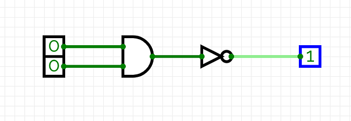
At first glance, this may seem complex. However looking thoroughly, and remembering the fact that all complex logic gates rise from the simpler ones, we can recognize that this is just a reversed and gate, meaning that the outputs of a normal and gate will simply be reversed. To construct this in our digital circuit simulator, we can first set up the and gate and simply place a not gate at the end:
If we try it for all the inputs:

We can see that it fits the Nand Truth Table perfectly. With this knowledge, what can we do? One interesting “function” we can create is a logical calculator. Because gates can only take in inputs of 1s and 0s, such a task is more difficult than it seems. The first way to understand bit addition is by creating a truth table for addition. Bit addition is not complex by itself, as it is just normal addition with a twist; Here is the truth table for bit addition:
2 inputs will result in 2 outputs, a result and the carry (which can be used for larger addition problems). To create our boolean circuit, we first have to distinguish between the result and carry, as they are separate outputs. First, begin with the result; The result truth table looks eerily like the Xor truth table, which is a very important distinction:
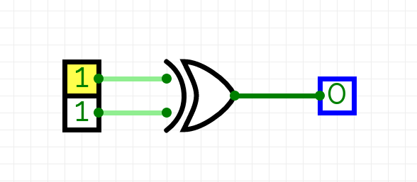
After recognizing this fact, we can begin implementing this into our circuit and check the truth table if it gives the proper result (under the result column).
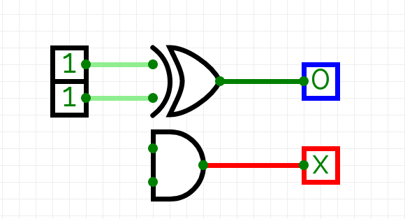
Note that both inputs are being added with each other, so 0 + 0 -> 0, 1+0-> 1, and 0+1 -> 1. However in the case of 1+1, we reach a problem. 1+1 in binary addition -> 10, but we only have one output. To remedy this, we can create another output for the extra carry. However we only need this carry output if the input is 1 and 1; Keyword is and, which is the exact gate we’ll use to establish this.
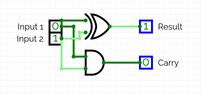
After some testing, we can see that it follows the 1-bit addition table from above.
To make this more complex, we’ll walk through creating a 2-bit adder, which just uses the one-bit adder with a few more additions. A simple 2 bit adder takes in 4 inputs, a 2-bit top addend and a 2-bit bottom addend. It applies the same operation as the one-bit addition circuit except 3 times (2 for the actual addition, and one extra for the carry). First, let’s setup the workspace, which requires 4 inputs and 3 outputs (The output can be larger than 11, so we need a 3rd bit). We will extend the inputs and outputs as needed.

Like mentioned before, we simply need to do the same addition problem, except three times (twice for each bit and an extra time for the carry of the 1st addition), and with a few modifications. While it is difficult to understand what we’ll be doing, I recommend doing a few 2 bit problems and creating a simple truth table for it. First step we need to do is add the right-most bits, which we can do easily with our simple adder:

After implementing this circuit, we just have to replicate it again for the left-most digits in our addends. We will be using the carry for the 2nd bit in the sum soon enough. Next, hook up the addition of the left-most bits, but don’t assign them to the results (we still need to deal with the carry)

The second to last step is to run through one more addition operation, adding carry to result2:

The last bit (and the last step) is fairly simple to arrive at: Its simply the logical carry2 or carry3:

After testing the calculator, we can see that it, indeed works. The captions are the binary form of the calculator’s input and outputs in decimal:


You’ll notice that, even when we use all the bits, we only arrive at 110. To get the complete 111, we’d need to modify our calculator to take in a carry as well, which is the only possibility of getting 111 in these circumstances.
That was a lot! I commend you for even scrolling this far down, and I hope you learned something!
To learn more, visit:
- Boolean Algebra
- George Boole
- Logic Gates
- De Morgan’s Laws and Karnaugh Map (boolean logic simplification)
- Computer Opcodes (Base instructions, in hexadecimal, to the CPU to do some calculations)
Visit my Github for higher-level programming projects, and issue pull requests for anything you want to add to any projects!
-Shynn Lawrence
